Designers: Lydia Hatfield, Mae-Lyn Leonard, William James, and Brian Castro
Client Coordinator: Dana Kropf, OT
INTRODUCTION
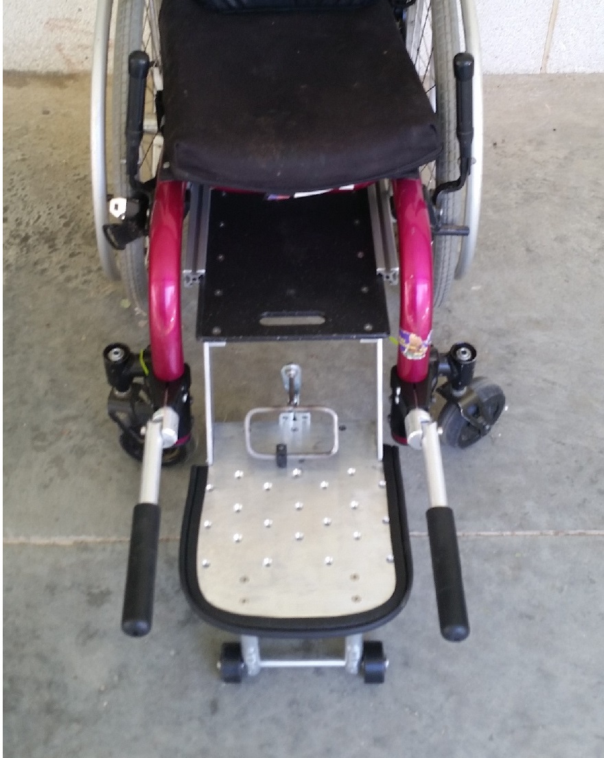
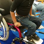
Figure 1: The device mounted to the wheelchair and extended out for use.
Molly is a five year old kindergarten student who was in an accident that left her with spinal cord injuries that resulted in paraplegia. Molly has damage to either the T4-T5 or T5-T6 regions of her spinal cord. Damage to these regions results in the loss of control of one’s legs and affects the control of the trunk to varying levels [1]. Because of this injury, Molly spends most of her day in a wheelchair. Being in a wheelchair diminishes her ability to fully interact and engage with her peers. During “carpet time” throughout the day children learn and play together on the floor. At present Molly can get out of her wheelchair independently through a method that combines sliding and lowering herself to her footplate and then to the floor. When it is time to return to her wheelchair, she is lifted back into it by her aide. This current method is not always practical or safe and seriously limits Molly’s much desired independence.
Currently there are few devices available on the market to assist children in transferring between their wheelchairs and the floor. One such commercially available device is the Bottoms Up Bar [2]. It is essentially a seat with hand grips that is placed in front of a wheelchair. Users slide themselves to the seat and then to the floor. The problem with this system is that it is not dimensioned to accommodate a child’s size and strength. We are not aware of any device designed to facilitate a child’s transferring independently between the wheelchair and the floor.
We developed a device that allows Molly to get in and out of her wheelchair with minimal to no assistance. Most importantly, the device or method must be safe and easy for the child to use. Since Molly already has a quick, though not very safe, method to get to the floor, the new system enables her to get to the floor quickly. The device also facilitates Molly’s independent return to her wheelchair and it is portable so that she can use it at home as well as in the classroom.
TECHNICAL DESCRIPTION
The device (Figure 1) fulfills the goal of offering Molly and others like her greater independence of movement. It consists of a fabricated unit of two platforms or seats arranged step-wise to slide like a drawer from under the seat of Molly’s wheelchair. It is anchored to the underside of the wheelchair by means of four aluminum tube clamps. The bottom seat stands safely 5 ⅞ inches above the floor with extendable foot pegs that make up the difference. The design allows Molly to scoot at will from her wheelchair down onto the floor and also to easily and safely lift herself, using wheelchair-attached handles, up the two platforms again before returning them to their resting position back under the seat. During typical wheelchair use with the steps retracted, the bottom step also functions as a footplate.
- Steps
The main aspect of the device is a two-step sliding staircase which fits in the extruded t-slot frame under the wheelchair. The sliding staircase is composed of a ¼ inch polypropylene top step fastened to a ¼ inch machined aluminum bottom step. The outside edges of the polypropylene top step fit into the inside facing slots of the frame assembly, and parallel aluminum runners line the underside of the step, just medial to the slots on the frame. This creates a track for the staircase to slide in and out of the frame assembly. The bottom step is fastened to the top step on its outside edges by two 3∕16 inch thick aluminum plates that make a 5 ½ inch space between the steps. Extended out, the device allows for a 5 ⅞ inch distance from the bottom step to the ground which is within the range that the client can lift herself. When the step assembly is in the stored position under the wheelchair, the bottom step is used as the client’s foot plate. The front and side edges of the aluminum step have been covered with a rubber trim guard to avoid possible scraping or irritation to the client’s back while the device is in use.
- The Extruded T-Slot Frame
The frame for the device is attached to the wheelchair using attachment clamps from Ki Mobility (Stevens Point, Wisconsin, www.kimobility.com). The top step slides in and out of the grooves of an extruded T-slot frame. The aluminum extruded t-slots that were used have a 1 inch extrusion size and a ¼ inch slot width. The edge of the top step rests inside the slot of the frame and slides along the track. On the underside of the frame are two aluminum crossbars that provide structural support for the frame as well as limit the step assembly’s extension and retraction to the intended range of motion. The device is prevented from being pulled too far forward by stop pins attached to the runners on the underside of the top step that contact the crossbars when the device is extended at its maximum. The T-Slot frame is dimensioned so that when the device is completely retracted it is directly under the client’s seat but is able to extend to a full 4 ½ inches for use.
- Handles
The pair of handles is permanently attached to the tubing of the wheelchair using the same clamps that are used to attach the frame assembly to the wheelchair. These handles are 12 inch long ¾ inch aluminum tubes covered with rubber grips. The handles are attached to a pivot joint that allows the handles to be stored and locked in a vertical position while not in use. The client uses these handles to move from the floor to the bottom step and to move from the bottom step to the top step. The device allows the client to use the frame of the wheelchair as the handles needed to assist in the transfer from the top step to the seat of the wheelchair.
- Foot Pegs with Locking Mechanism
In order to prevent the wheelchair from tipping forward with the device and to reduce the amount of total possible impact force sustained by the wheelchair, the bottom step has locking foot pegs, attached that meet the ground when the device is in use. The foot pegs are fabricated from ¾ inch aluminum tubing and are mounted in a one-directional bracket to the underside of the foot plate. The foot pegs are connected to each other by a 5∕16 inch axle with nylon wheels on the distal sides of the foot pegs. Attached to the axle of the foot pegs is a two-point-rotating rod linkage similar to a shift linkage on a car. The other end of the linkage is connected to a toggle clamp mounted to an aluminum extruded t-slot on the backside of the footplate. The toggle clamp pushes and locks the foot pegs out when the user pulls the clamp handle forward for use. When not in use, the foot pegs are pulled up and locked under the step by pushing the clamp handle backwards.
REFERENCES
[1] Shepherd Center. (2013). Levels of Injury [Online].Available: http://www.spinalinjury101.org/details/levels-of-injury:
[2] AbleData. (2013, February 3). Transfer Aid: Bottoms Up Bar [Online].Available: http://www.abledata.com/abledata.cfm?pageid=19327&top=12645&ksectionid=19327&productid=204609&trail=0&discontinued=0:
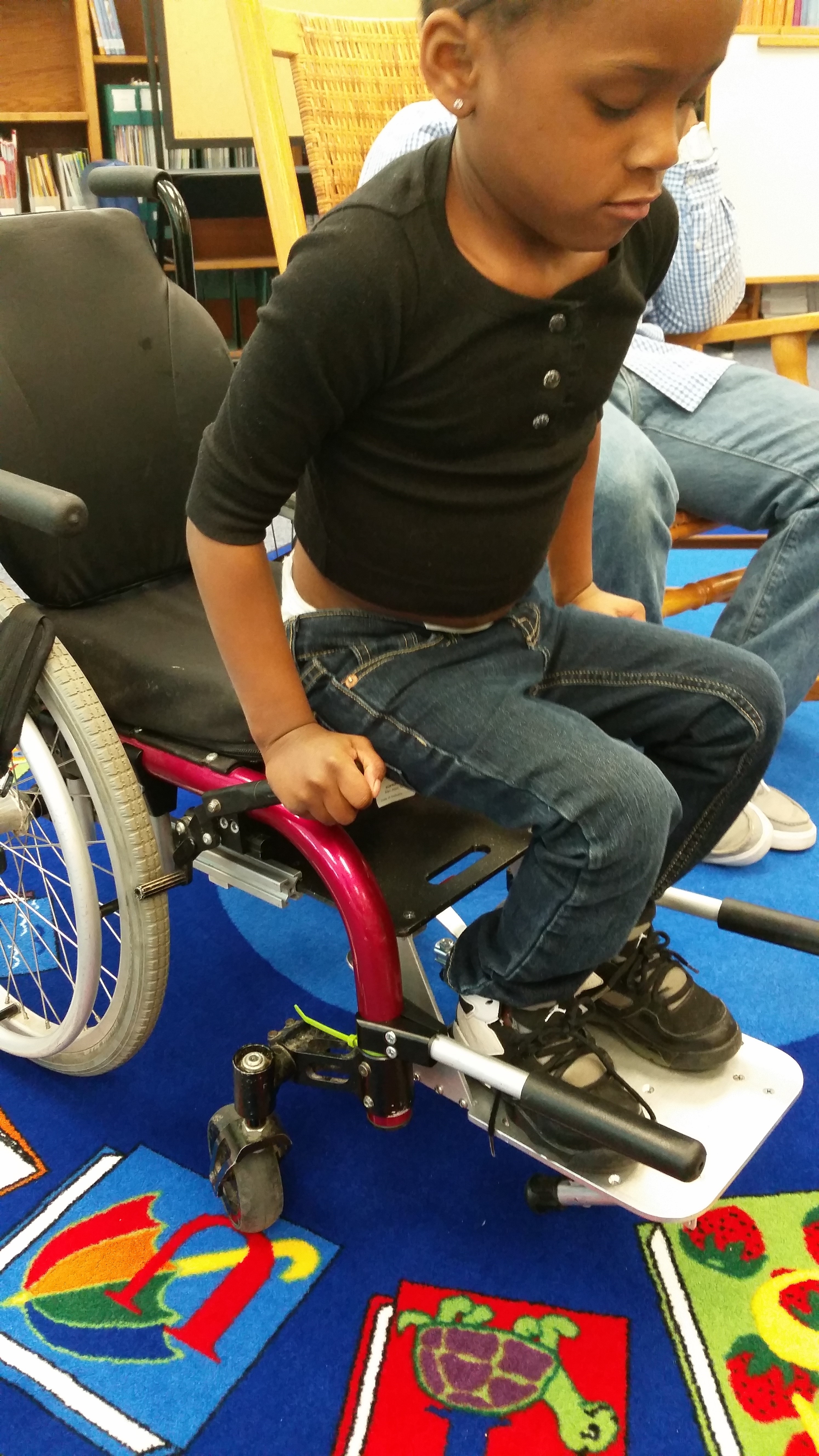
Figure 2: The client using the device
University Operator: (919) 962-2211 | © 2024 The University of North Carolina at Chapel Hill |