Designers: Jay Fisher and Rick Uhlir-Hall
Client Coordinator: Luanne Holland, Speech and Language Pathologist, Durham Public Schools
INTRODUCTION
The sensory play gym is designed to accommodate an eight-year-old girl with cerebral palsy, hearing impairments, and severe visual impairments. She has limited movement control of her head, hands, and feet. Her favorite position is in a side-lyer. Proper sensory development relies heavily on a child’s potential to interact with various stimuli. However, it is difficult to set up switches and stimuli for the client while she is in her side-lyer. The device allows the therapist to position many sensory stimuli in locations easily accessible to the client. Once the inputs and outputs are in place, the sensory play gym allows the client to explore her environment independently while receiving vital sensory stimuli.
SUMMARY OF IMPACT
Prior to the design of the project, the client could not benefit from sensory stimuli without additional help. The play gym allows her to interact without the aid of others. Her physical therapist said, “The sensory play gym will open new doors for her. The sensory play gym will allow her to enjoy a variety of self-initiated sensory experiences that she could not be able to have otherwise. These experiences will help her to learn cause and effect, communication skills. Self-initiated movement will also facilitate improvements in active range of motion of her arms and legs. She really loves it!”
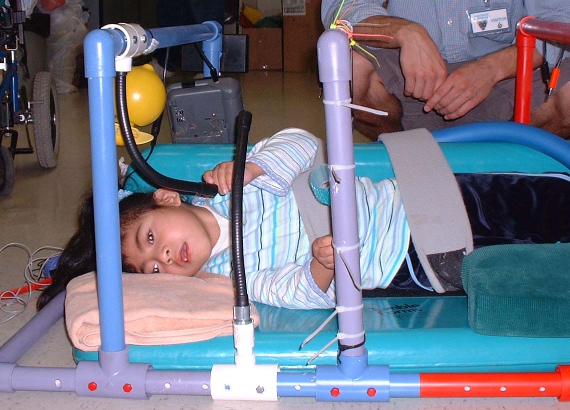
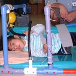
Figure 1: Side-lyer
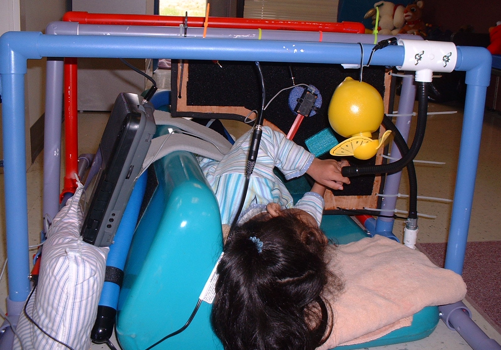
Figure 2: Arches
TECHNICAL DESCRIPTION
The base structure of the play gym fits around the client’s side-lyer (Figure 1). The three detachable arches that complete the frame can be connected in different places along the rectangular base to fit the needs of the client. The input switch plugs are located at the base of the each arch. Clamps can be used to position the switch within easy reach of the child’s head, hands, or feet. The output stimuli are connected to the top of each arch.
Each arch functions differently. One arch contains two input jacks directly wired to the two output plugs. Any commercial switch can plug into the input jacks and stimuli (tape player, fan, etc.) can plug into the output plugs. When the switch is pressed, it turns on the stimulus. When the user releases the switch, the stimulus turns off. A second arch contains the same direct circuitry; however, it also has a Velcro covered piece of plywood attached to the inside of the arch (Figure 2). The wall edge is covered with padding to prevent injury to the client. By attaching different switches, toys, and materials of various textures to the Velcro, the therapist can place stimuli at the client’s fingertips. The third arch contains one input jack connected to three different output plugs via an electronic toggle circuit. Activation of the switch connected to the circuit will cause the first output to turn on for 10 seconds. The next activation of the input causes the second output to turn on for 10 seconds, and likewise with the third activation. On the fourth activation of the input switch, the circuit will cycle back to the first input.
The sensory play gym is constructed out of one inch diameter PVC tubing, selected for its small size and rigidity. Angled “L”-shaped pieces are used to connect the corners of the rectangular base frame. The base frame contains four different regions, each containing five holes spaced one inch apart. This allows the arches to be moved as needed. The arches are locked into place using a “T”-shaped piece at the base of the arch and two plastic coated bolts.
To protect the client, the wiring of the play gym is contained within the PVC tubing of each arch. One-eighth-inch standard audio plugs and jacks are used, making the device compatible with existing switches and toys. The toggle circuit is inside a plastic enclosure, which is attached to the PVC tubing. A PIC16F877 microcontroller (Microchip, Chandler, Arizona) controls the circuit; it sets one the three output pins to 5V for 10 seconds whenever the client presses the input switch. The ULN2003AN drives a relay switch to turn on the appropriate stimulus.
The approximate cost of the project is $200.
University Operator: (919) 962-2211 | © 2024 The University of North Carolina at Chapel Hill |