Designers: Sarah Jastram and Parth Tarasaria
Client Coordinator: Tracey Craven and Amanda Crawford, OE Enterprises
INTRODUCTION
OE Enterprises trains people with learning disabilities and limited dexterity to do contract work at their facility. One of the jobs involves collating and packaging paper brochures using a commercial heat shrinking machine, which is in need of adaptations for safer use by operators who are seated in a wheelchair and/or have limited dexterity. The heat shrink machine is operated as follows: the user gets a stack of documents to be wrapped and places them on the loading station between two layers of plastic. Still wrapped in plastic, the user pulls the documents by hand to the pressing station. Once in the correct position, the user grabs an L-bar arm containing a hot wire and lowers it onto the plastic sheathed document. This cuts and seals the plastic around the documents. The arm is then lifted back up and the document is moved to the heat shrink tunnel.
The machine is designed to be used from a standing position, and many employees at this facility cannot stand for extended periods because of their disability. In addition, some of the steps are difficult for employees with poor motor control. Finally, the machine uses a hot wire to cut the plastic material, which presents a safety hazard. To address these issues, we modified the heat shrink machine in order to make it accessible, safe, and easy to use for users with limited dexterity and users in wheelchairs. The individual goals were to: improve the ease of sliding the documents from the loading station to the pressing station in a neat fashion; extend the L-bar arm so that it is easy to reach from a seated position; and protect the user from burning hazards.
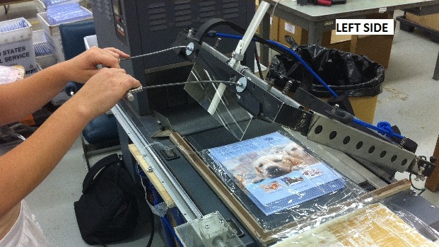
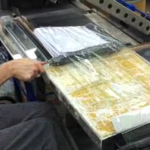
Figure 1: (a) the pressing station
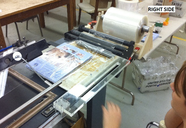
Figure 1(b): the loading station and spool of plastic shrink wrap
SUMMARY OF IMPACT
We observed several OE clients use the modified heat shrink machine and they said that the modifications made it much easier to use the heat shrink machine. OE Program Services Manager Amanda Crawford remarked that “Before [the machine] was not very accessible to people in wheelchairs or that have mobility issues or have difficulty with upper body strength. Now it is easier to pull down, pull the plastic wrap across the machine, and makes it overall easier for some of our individuals to use it.”
TECHNICAL DESCRIPTION
The modifications made to the machine were split into several parts: a push slider that pushed the documents from the loading to pressing station; a roll holder that facilitated the distribution of the heat shrink plastic; an arm extension that enables the user to easily lower the L-bar arm from a seated position; and a retractable shield that shields the hot wire from the user, while the L-bar arm is in the up position.
The push slider enables the user to easily move the plastic sheathed documents from the loading to the pressing station on the heat shrink machine. It also keeps any hands and fingers away from the dangerous hot wire. The slider is in the shape of a backwards “L”. The long arm of the L acts as a pusher that pushes the documents, and the perpendicular arm serves as a handle for the user and a connection to a linear sliding track. The pusher sits behind the document by default; the user grabs onto the handle and pushes against the document towards the pressing station. After sliding the document to the pressing station, the user then slides the pusher back to its default position.
The push slider was made from L-shaped acrylic plates bolted together to give it the thickness it needed to push the documents. The front edge of the plates have a slit that provides a handle for the user. The pushing edge of the plates have rubber along the bottom in order to provide better contact with the documents that they are pushing. The slider is attached to a linear rail to provide smooth, repeatable movement of the documents for individuals with poor motor control.
The heat shrink plastic comes in large, heavy rolls. In order to facilitate the pulling of the plastic from the roll, we designed a holder that utilizes an 18” conveyor belt roller. This roller contains steel ball bearings for smooth rotation even under a heavy load. The roller’s axle rests on two panels of wood placed on either end. These two side panels are reinforced with a bottom panel that holds the vertical panels upright and prevents the holder from tipping over when lateral force is applied. The wooden holder was clamped to a table that sits adjacent to the heat shrink machine.
In order to facilitate operation of the L-bar cutting arm from a seated position, we designed an extended handle that attaches onto the cutting arm. We also mounted a gravity-operated retractable shield that blocks user from touching the hot wire when the arm is up and retracts when the arm is pressed down. The arm is made of acrylic. The weight of this mechanism prevented the L-bar arm from automatically springing to the up position when not in use. Therefore, we attached bungee cords to the backside of the L-bar arm. This allowed the arm to retract automatically to the up position.
The total cost of these adaptations is $300.
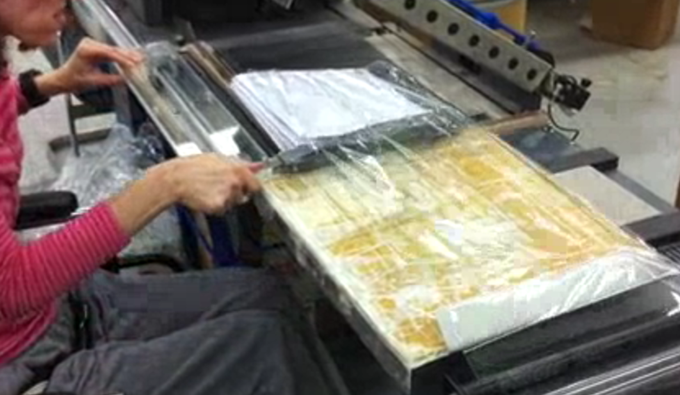
Figure 2: Client using the heat shrink machine
University Operator: (919) 962-2211 | © 2024 The University of North Carolina at Chapel Hill |