Designers: Andres Afanador and Laura Malone
Client Coordinator: Kevin Caves, ME, ATP, RET, Duke University, RERC on Communication Enhancement
INTRODUCTION:
The Switch Relay was designed to give clients control over two different switch-activated devices using only one switch. Pressing and releasing the switch will directly control the first device. However, when the client presses the switch for a minimum duration of time, the device toggles its state so that the switch now controls a second device. A knob allows the client to adjust the minimum pressing duration to 0.5 to 8 secs, in 1 sec increments. Subsequent switch presses that are longer than the minimum duration will toggle control of the Switch Relay between the two devices. An LED readout shows which device is being controlled.
SUMMARY OF IMPACT:
Allowing operation of multiple devices with one switch increases the independence of the user. The use of only one switch to operate a pair of devices also minimizes confusion for the user.
Because of the adjustable “hold time,” devices with different activation times can be operated; therefore, almost any switch activated device can be controlled with the Switch Relay. The coordinator of the project states that “the device will enable people with limited physical ability to independently operate multiple devices.”
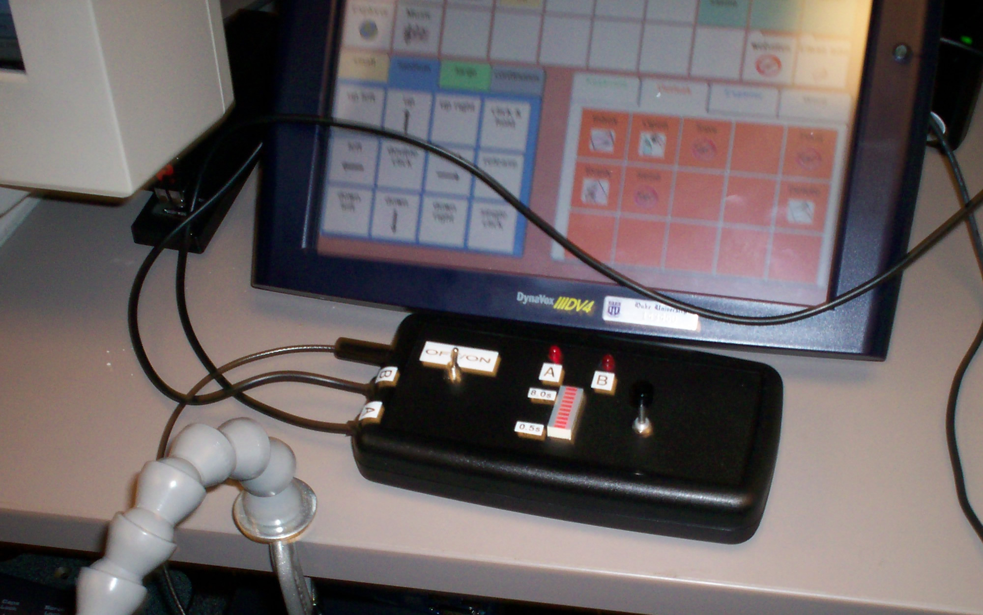
Figure 1. The switch relay device is attached to a PC and to a communication device. The client can use the same switch to activate the device or toggle control between the two devices.
TECHNICAL DESCRIPTION:
The Switch Relay circuit is based on a PIC microcontroller (Microchip, Inc., Chandler AZ), which detects the activation of the user’s switch. The PIC can determine the amount of time the switch is held, and then either change devices or continue to operate the current device. Latching SPDT relay switches (Omron G6EK-134P) were used to electronically isolate the output devices from each other and the input switch. The use of latching switches allowed for reduced power consumption, because they require a pulse for activation rather than a continuously applied voltage. Transistors (2N222A) were used to apply sufficient current to the relays.
The adjustable “hold time” is set using a potentiometer, which is read by the A/D converter of the PIC. LEDs indicate which device is under the control of the switch. An additional LED light bar indicates the length of the “hold time.”
The electronics are housed in a 3.5” x 7.0” plastic project box. Two mono 1/8” audio cables are attached in order to connect to the devices. A standard 1/8” mono audio jack is used as the input terminal, to which the switch is attached. The device is powered by a 9V battery with a regulator controlling the voltage applied to the circuitry.
The total cost of the device is approximately $40.
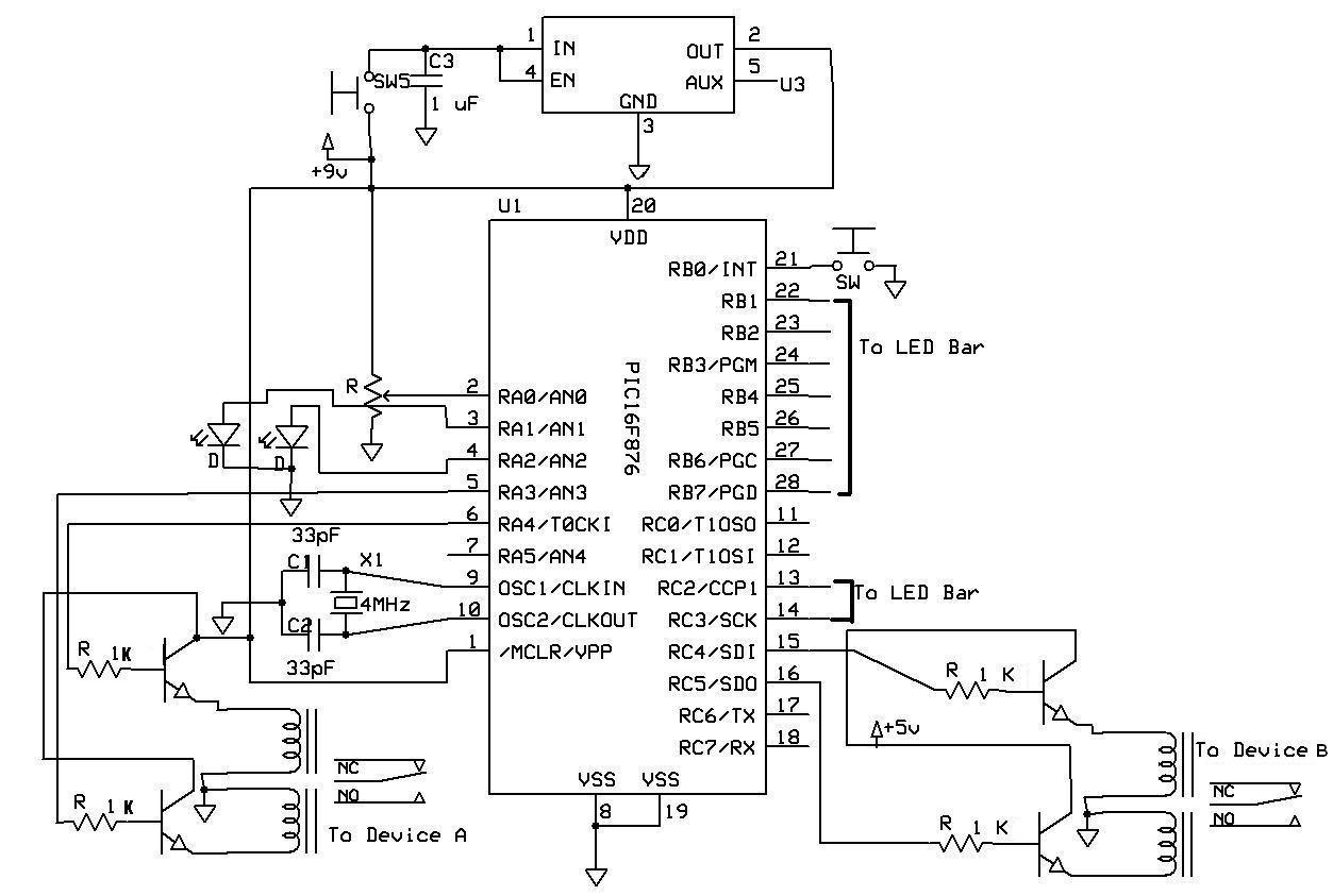
Figure 2. The switch relay circuit diagram. The primary components are a PIC and a pair of latching relays that control activation of either device.
University Operator: (919) 962-2211 | © 2024 The University of North Carolina at Chapel Hill |