Designers: Swaroop S. Singh, Vinay Tannan
Client Coordinator: Kevin Caves, Duke University Medical Center
INTRODUCTION
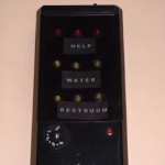
Amyotrophic Lateral Sclerosis (ALS) occurs due to degeneration of motor neurons in the brain and spinal cord. People affected by ALS or similar conditions have a constant need for communication with a personal attendant. This may be accomplished using a simple device like a doorbell buzzer. The patient presses a switch next to the bed and a buzzer (carried by the attendant) alerts the attendant. In current devices, the attendant is unable to differentiate between an emergency case and a non-emergency case when buzzed. This can add additional tension on the attendant and, as a consequence, could affect the quality of patient care. We developed a device that improves communication by allowing the patient to send one of three different messages to convey their needs. Possible messages shown in Figure 4 are “Help”, “Water”, and “Restroom”. In addition, the device features the option to emit different tones for a specific message.
SUMMARY OF IMPACT
The patient is able to communicate specific messages to the attendant efficiently. The attendant, aware of the patient’s exact needs, is able to work in a more calm and relaxed manner. Since the number of non-emergency instances is more than emergency instances, this device would significantly reduce the tension on the attendant. Both the transmitter and receiver unit are easy to operate, taking little time to learn. Messages on both units can easily be changed depending on patient needs.
TECHNICAL DESCRIPTION
The patient and the attendant each have their respective unit. On the patient unit, there are three different messages, which can be written on a piece of paper and inserted into the message text slot. The unit cycles through each message, indicating the current message by turning on LEDs (light emitting diodes) located underneath each one. When the patient has a need, he or she simply presses the hand switch while the desired message is illuminated. For example, if the patient needs water, the button is pressed when the “water” indicator is on. A radio signal is then sent to the attendant unit. The attendant unit has the same set of messages as on the patient unit. These are also written on pieces of paper and inserted into message text slots over a bank of LEDs. When the unit receives a message, it illuminates the corresponding message to indicate what the patient needs. Also it alerts the attendant that a message has arrived through audible (a distinct tone and a recordable audio message), visual (the LED indicator), and physical stimuli (a pager motor vibrator).
Any standard commercial switch plugs into the 1/8’ jack on the patient unit; it can be changed to suit the patient’s abilities. The unit receives power from a commercial 9V transformer plugged into the wall. A Basic Stamp 2 (Parallax, Inc.) microprocessor is used to scan the input from the switch. Each message is coded with a numeric value. On selection of the message the numeric value is transmitted using a commercial 418 MHz RF (radio frequency) communication board (Parallax, Inc.). The default message on the unit is “Help” and it is always activated when the switch is pressed for an instant. Additionally, LEDs flash in sequence when no switch is detected on the unit. The programming for the microprocessor was done in the Basic Stamp PBasic language.
The attendant unit (powered by a rechargeable 9V battery) is light, durable and handheld. A Basic Stamp 2 microprocessor integrates the various operations of the unit. The unit has a commercial 418 MHz RF receiver board (Parallax, Inc.). The current signal from the microprocessor is amplified with an NPN transistor 2N2222A and is used to power the pager motor. Similar circuits are used to power the LED banks and the audio circuit. The pager motor is attached to the underside of the unit and vibrates when turned on. Depending on the numeric code received, the appropriate display lights up. The display on this unit consists of three banks of LEDs arranged in parallel rows of three each. As in the patient unit, the messages are placed over the LEDs and are highlighted when the LEDs flash. The microprocessor also sends out a tone to the speaker, with its intensity controlled by a potentiometer. There is a specific tone for each message. Pressing the switch on top of the unit can reset the entire unit. Additionally a SPST switch provides an option to turn off the vibrate alert. The programming for the microprocessor was done in Basic Stamp PBasic as well.
Approximate cost for the entire device was $325.
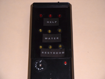
Figure 4. The Personal Attendant Call – attendant and patient unit
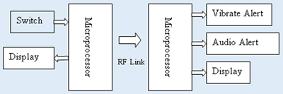
Figure 5. System Block Diagram (transmitter on left, receiver on right)
University Operator: (919) 962-2211 | © 2024 The University of North Carolina at Chapel Hill |