Designers: April Chambers and Tim Humble
Client Coordinator: Julie Olinic, Speech and Language Therapist
INTRODUCTION
Visual impairment affects many people, and it can impact their mobility, learning, and self-esteem. While some individuals have trouble seeing any object, those with moderate impairments may be capable of seeing but have difficulty in tracking objects across their field of vision. The introduction of tracking devices to stimulate and exercise the visual system can help to correct the impairment. Currently, teachers and therapists do this by manually moving light sources across the student’s field of view.
Fig 1: Students and faculty testing the tracking device
SUMMARY OF IMPACT
This device is designed to improve the vision of students with disabilities. It encourages them to track an object throughout their field of vision by providing visual stimuli (blinking lights) and auditory stimuli (music or recorded messages). The therapist uses a remote control to move the stimuli through the student’s field of vision, and to turn the stimuli on and off.
This device implements several improvements over currently tracking techniques. Since the therapist controls the device remotely, they are positioned behind the student and the student can focus on the stimuli in front of them without being distracted. In addition, auditory stimuli supplement the visual stimuli to help engage the student’s visual tracking abilities.
TECHNICAL DESCRIPTION
The block diagram in figure 1 shows the system components and a photo of the prototype is shown in figure 2. The tracking device consists of four parts: the transmitter, the receiver, the robotic arm, and the stimuli. The stimuli are attached to the end of the arm, and contain both visual and auditory components. LEDs are arranged around bright pictures on a card to provide the visual stimulation. The auditory stimuli consist of well-known songs. For the students with weaker vision, the songs are the central stimuli used to attract their attention. For others, the songs are used to reward the students after successfully tracking an object. The cards are removable, and the bright pictures are attached with Velcro to allow for variety. Two stationary arms can also be attached so that multiple cards are visible. This allows the teacher or therapist to have the student choose between the cards.
The robotic arm has motion in three directions: vertical, horizontal along an arc, and horizontal along a radius (towards and away from the student). Motion in the vertical and horizontal dimensions is controlled remotely by the therapist, and it moves the stimuli across the student’s field of vision. Radial position is adjusted manually, allowing the teacher to decide how close the card(s) are to the student.
The mechanical design of the robotic arm consists mainly of two vertical shafts, and one horizontal telescoping pole. The tall vertical shaft allows for gross movement (up to six feet) through a rack and pinion system, which the user controls manually. This is in order to incorporate students who are both sitting in wheelchairs and those strapped in the standers, in which the student is standing up. The shorter vertical shaft allows for vertical movement via the remote control. The range of vertical motion for this shaft is one foot. A dc motor, obtained from an auto junk yard, drives this movement by turning a screw, which then raises or lowers the shaft. The horizontal movement is controlled by a second dc motor using a pulley system (figure 3). When the motor is activated it rotates the shorter vertical shaft to create right and left movement. The telescoping pole is attached to the end of the vertical shaft. The object card is attached to the end of the pole, and the teacher can manually control the distance from the card to the student.
The transmitter circuitry is contained within the hand-held remote control. When a key is pressed on the keypad, a Basic Stamp microcontroller sends out a code containing information about the row and column of the key pressed. A Linx transmitter chip (Linx technologies, Grants Pass OR) amplitude modulates this signal at 300MHz.
The receiver demodulates the 300 MHz signal from the remote control. A Basic Stamp microcontroller (Parallax, Rocklin CA) interprets the received code and activates the appropriate secondary circuits. The dc motors are controlled through the use of relays, and additional circuitry activates the playing and recording of messages and music.
The device incorporates approximately $500 in electrical and mechanical parts.
Figure 3: The prototype device. The long vertical shaft is on the far left, and the short vertical shaft is next to it. The sensory stimulation card is in front of the subject.
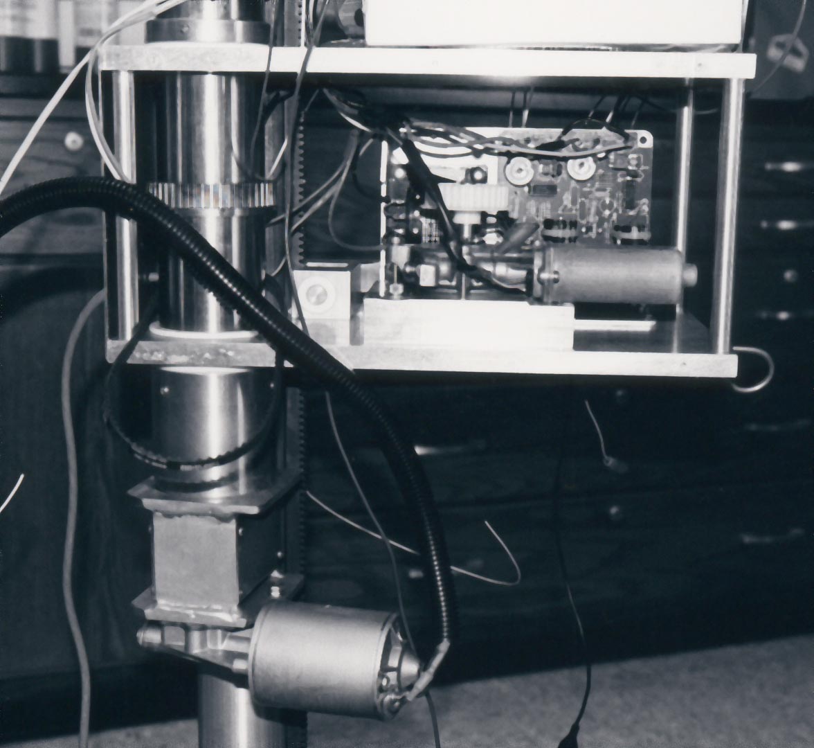
Figure 4: This enclosure contains a dc motor in the foreground, and a power supply behind it. The motor turns the vertical shaft, on the left through a pulley (not shown) with teeth that grab onto each part.
University Operator: (919) 962-2211 | © 2024 The University of North Carolina at Chapel Hill |