Designers: Vaibhav Hans, Jacob Turpin, Shruthi Rajan, and Ankit Patel
Client Coordinator: Dr. Jongbae Park, UNC Physical Medicine and Rehabilitation
INTRODUCTION
The UNC Physical Medicine and Rehabilitation department specializes in integrative medicine and technology development in rehabilitation. Through alternative medicine and acupuncture therapy, our client Dr. Jongbae Park treats patients that are affected by chronic pain in the neck, lower back, and knees, as well as other temporomandibular joint conditions. Traditionally, physicians employ pain medication, mechanical pressure, and other painful and time-consuming methods to alleviate these conditions. However, Dr. Park, who is well versed in both Korean and Western medicine, believes the origin of these conditions lies in the pelvis, specifically in the pelvic posture. The pelvis, a key anatomical structure involved in the stability of the human body, when misaligned, can produce symptoms such as back pain, improper posture, indigestion, and overall, inhibits efficient organ function. The central premise of Dr. Park’s approach conveys that if poor pelvic posture can be eliminated efficiently and non-invasively, many such symptoms can be avoided.
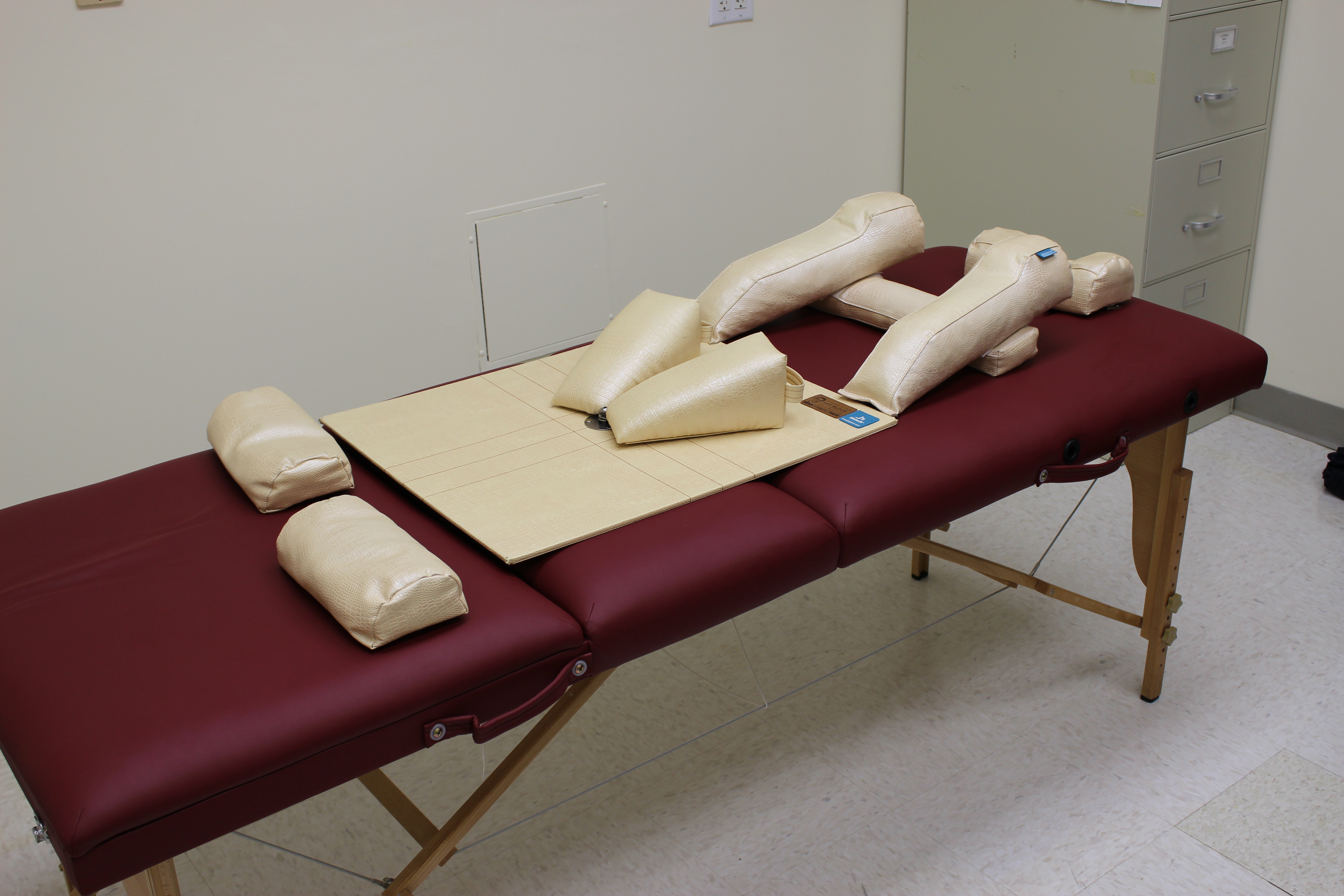
Figure 1: The commercial Pelvic Balancer on a therapy table
Dr. Park utilizes the commercially available Pelvic Balancer apparatus in his therapy sessions to attempt to straighten the pelvic posture of his patients. The apparatus is split into various correctional parts on which the patients lay down. Each correctional part, as shown in Figure 1, is adjusted by Dr. Park during treatment until the patient’s weight is equally distributed along the whole apparatus. Dr. Park’s current course of action, when using the balancer, is largely dependent on speculation.
The goal of the project is to develop a feedback mechanism that can be incorporated into the current Pelvic Balancer to collect and store real-time force data. This will provide quantitative feedback to improve Dr. Park’s ability to predict the efficiency of his treatments. Furthermore, these real time measurements during treatment will allow Dr. Park to track patient progress and accurately position the assorted correctional parts.
The device must be suitable for repeated use in a clinical setting. Therefore, it must have minimally exposed electronics, be durable to repeated wear, and be easily disinfected. Additional features such as low size and weight to facilitate easy movement and storage must also be considered. Most importantly, the device’s success will be gauged upon the ability to: (1) provide consistent and accurate pressure measurement that quantify patient balance, (2) adjust to varying body sizes/types, and (3) record measurements to an external location.
TECHNICAL DESCRIPTION
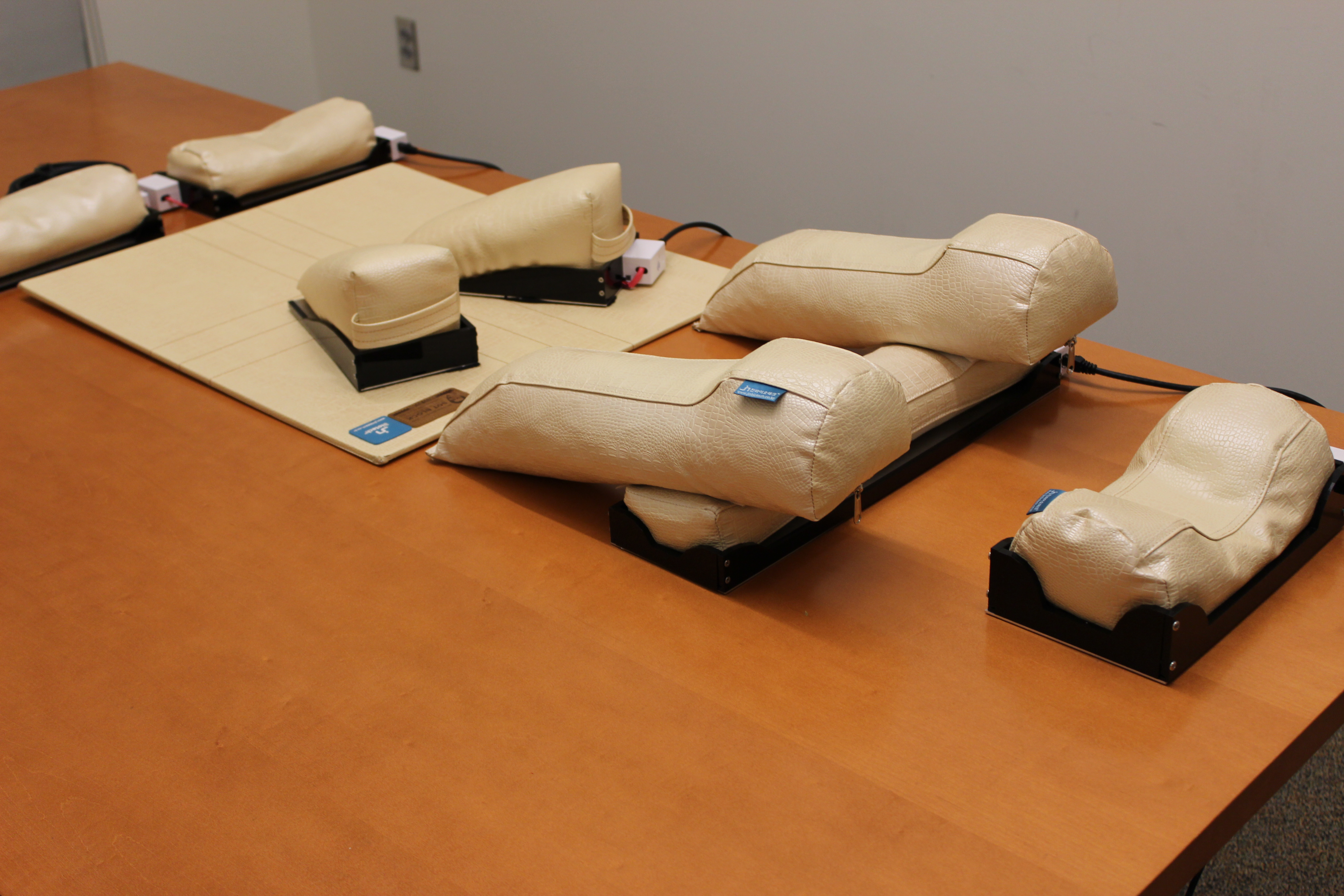
Figure 2: The force sensors placed under the pelvic balancer cushions
Our device is incorporated into the commercially available Pelvic Balancer, which is a compartmentalized system of correction parts used during treatment to realign misaligned pelvises. Our device uses a quantitative sensor-feedback system on each correction part, and it relays real-time force measurements and record changes in patient treatment. The main components of this device include acrylic-aluminum mechanical cases to house the correction parts and Flexi-force pressure sensors, a built-in electronic circuit and microcontroller, and a user interface system. The device only provides additional information to benefit the client’s treatment and does not interrupt the client’s regular procedures of using the system.
- Mechanical Housing
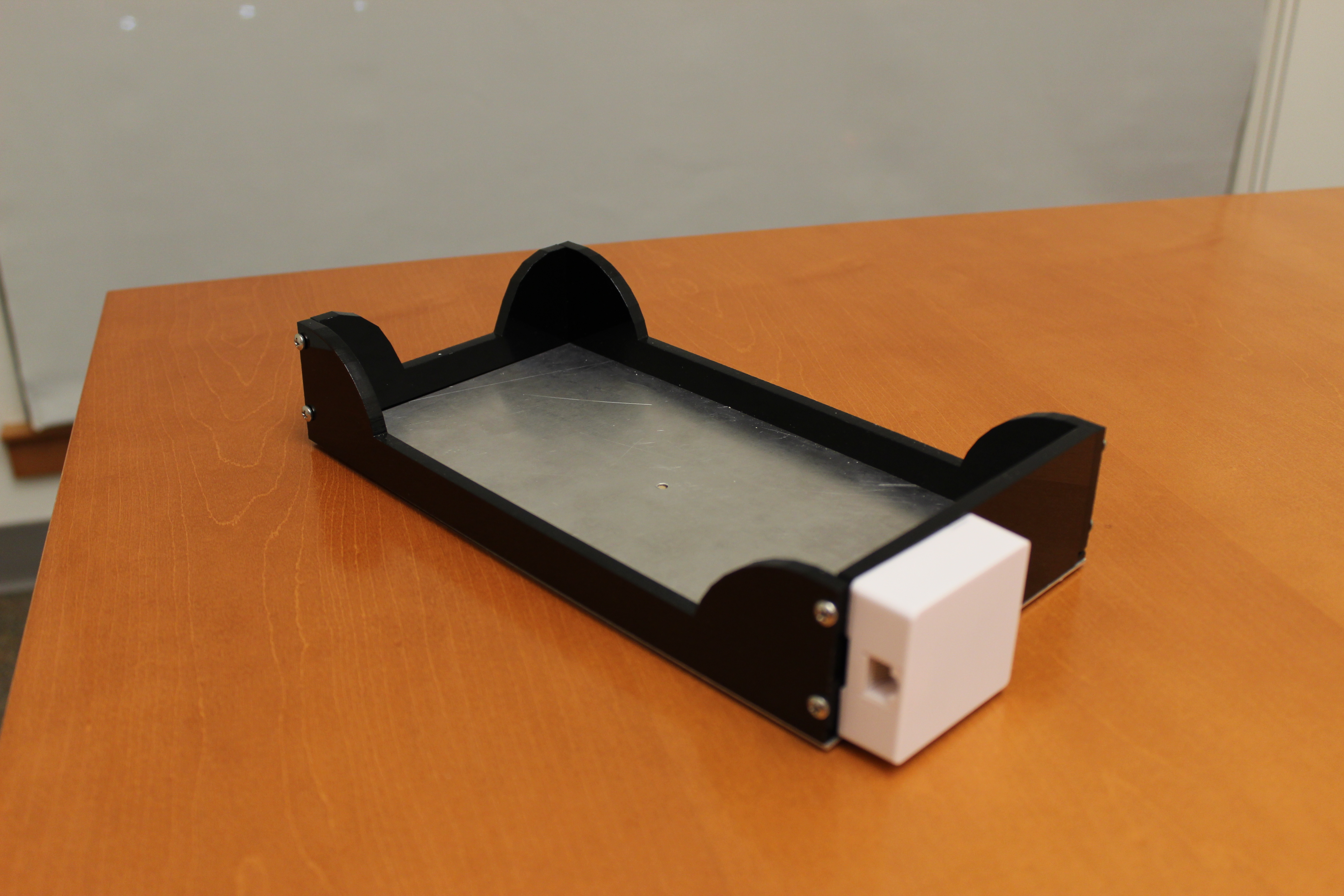
Figure 3: The mechanical housing that contains the force sensors.
The mechanical housing component is a dual structure consisting of acrylic and aluminum parts to house the correction parts and enclose the sensors. The base of the structure is a double-layer of 0.06 in aluminum sheets. After consulting with Dr. Lewek, an expert in rehabilitation instrumentation, it was decided that aluminum would best help maximize the compressive response from the sensors. The components of the measuring plate apparatus include a base plate, two small circular disks (to form a conical contact surface to the sensor), and a top plate (which comes into contact with the cushion).
To hold these plates in place and around each individual cushion, acrylic casings were designed specifically to imitate the shape of each correction part. Since the patient body will not be placing any direct force on these areas, acrylic proved to be the most cost efficient and durable material. The rectangular sides of the acrylic structure are one inch in length in order to ensure that the correction parts snuggly fit on top of the aluminum sheets. The acrylic structures were modeled with sliding rails for the aluminum base to slide on at the bottom. To lock the plates into place and hold the protruding discs in place, a combination of rods and flathead screws were used.
- Electronics
- Sensors
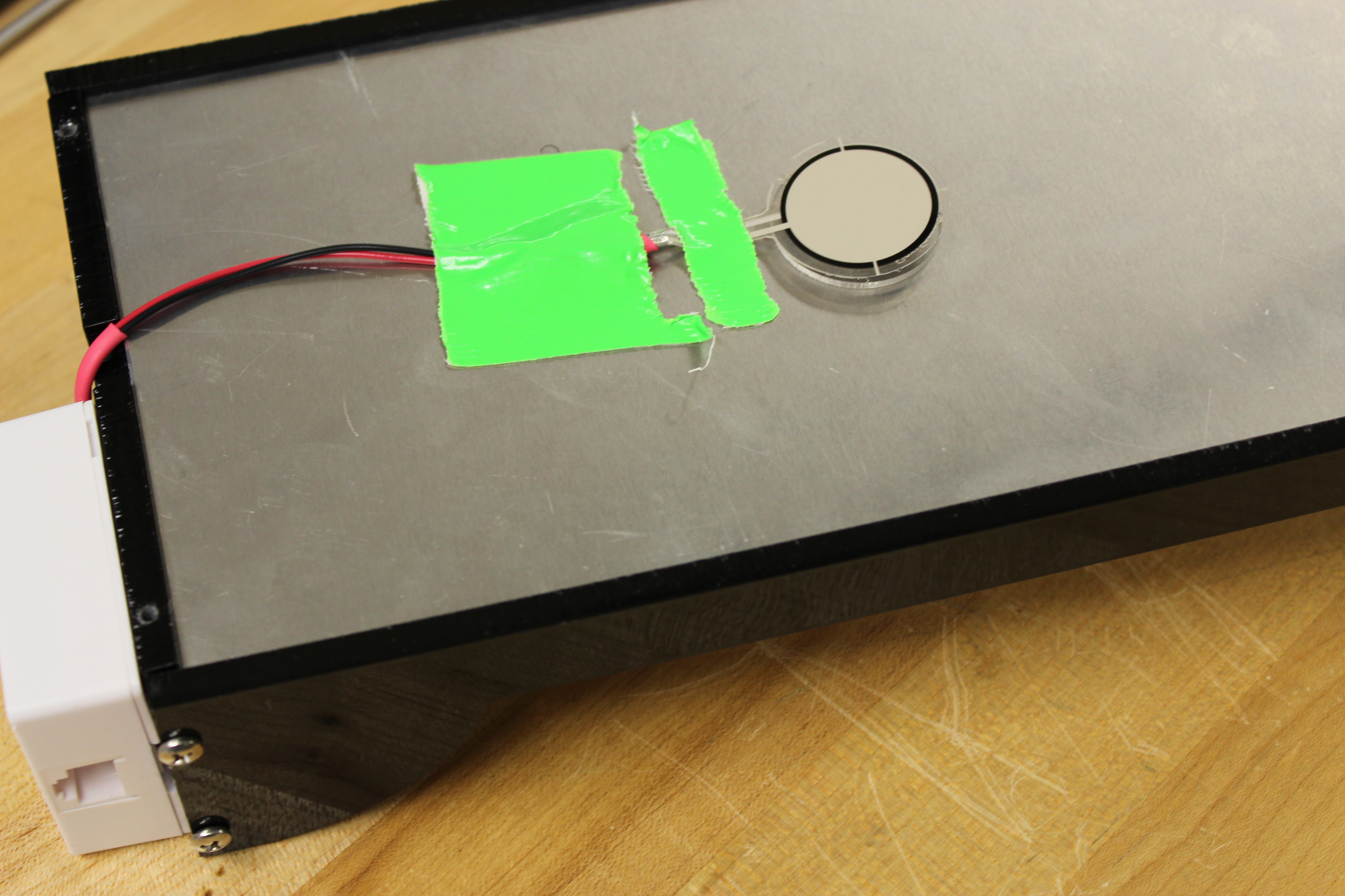
Figure 4: Flexi-Force piezoelectric sensors
Flexi-Force piezoelectric sensors (Tekscan A401-25) were incorporated below each correction part and used as the primary measurements of change in force. These sensors proved to be most rigid and allowed for the maximum weight capacity of 2000 lbs. The A401 sensors also provide the Pelvic Balancer with the flexibility it needs to be used for a wide range of patient weights and sizes. The goal of these sensors is to measure the force at each correction part as well as the force differences between corresponding left and right correction parts. By placing sensors underneath each correction part, it is ensured that the patient’s weight will be equally distributed along the cushions and on to the sensor’s surface. The sensors were connected by wire to the microcontroller and electric circuit housed outside the device.
Although the manufacturer recommended using the sensor in an inverting amplifier configuration, it was determined by experimentation that this is unnecessary; by connecting this sensor in a simple voltage divider circuit, viable readings were achieved. Further, in this configuration, the sensitivity of the sensor could be changed easily by changing a single resistor. Therefore, for each correction part, a different resistor was used based on the size of the piece and the number of sensors within the measuring plate apparatus.
- Microcontroller
The Arduino Mega microcontroller chipset was chosen to facilitate the transmission and receiving of data from the sensor to the computer. This particular microcontroller was chosen due to its various in-built features such as standby capabilities, availability of numerous analog inputs, and compatibility with Processing. The sensors operate by converting point force measurements into electrical signals that are received by the microcontroller. The microcontroller acts upon these signals using programming and passes them via RJ11, the standard telephone cable, to a computer. The Arduino Mega also a good choice for further expandability as there are many additional attachments available such as Bluetooth shields to allow this device to be updated in the future without a complete redesign.
- Control Unit
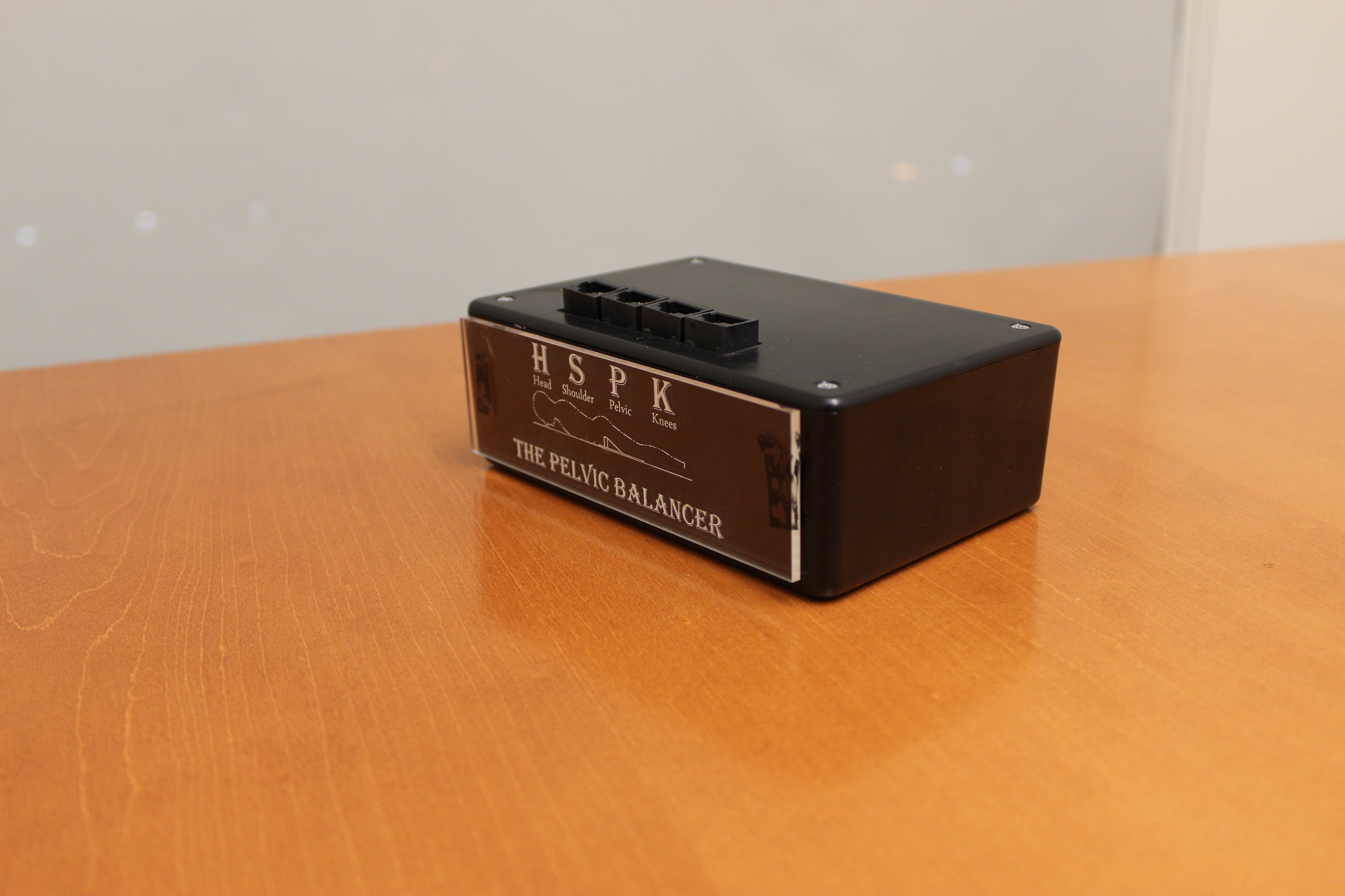
Figure 5: The control unit
In order to keep the device portable, which is especially important for when Dr. Park is setting up the device on the examination table, the control unit was created as a separate entity that is not permanently attached to the measuring plates. To allow for easy reconnection between the sensors and the control unit before every session, RJ-45 connectors were used. The corresponding cables for this connector, known more commonly as telephone cables, will be removable from each of the pieces to allow for easy device storage and setup. Further, the abundant availability of various types and lengths of telephone cables will allow Dr. Park to replace cables without any problems.
- User Interface and Programming
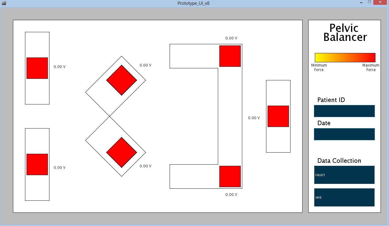
Figure 6: Screenshot of the PC user interface
The user interface is the part of the device that Dr. Park and other clinician will interact with the most. The programming behind the UI contains processing that converts the voltage measurements read from each of the sensors (from the microcontroller) into force measurements. This processing is calibrated for each individual piece, based on size of the cushion and number of sensors. The end-user software of the device is Processing, programming software created by MIT for graphically representing data using the programming language JAVA. The user interface operates by displaying a layout of the Pelvic Balancer on the patient bed, including each correction part. Colored squares are projected on top of the whole apparatus to represent the sensors. The color of the sensor squares changes, corresponding to the applied force at each sensor. The numerical value of each sensor is displayed as well. On the right side of the user interface, separate controls allow the user to choose various settings and collect data. Although all the data points are being collected in real-time, with the addition of the collect button, Dr. Park can store that data point into another column in order to highlight it for prolonged patient progress tracking Data that is collected using these buttons can be saved into CSV files, a standard type of file that can be opened in common spreadsheet software such as Microsoft Excel.

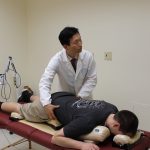
Figure 7: Dr. Park treating a client in the pelvic balancer.
University Operator: (919) 962-2211 | © 2024 The University of North Carolina at Chapel Hill |