Designer: Rocco DiSanto
Client Coordinators: Margie Muenzer, PT, and Lissa Lutz, instructor, NC Therapeutic Riding Center
INTRODUCTION
The primary client for this project is Jim (pseudonym), a young adult who participates in horseback riding at the North Carolina Therapeutic Riding Center (NCTRC). Jim has been diagnosed with spastic quadriplegia, cortical field vision, and uses a wheelchair. Jim is able to independently maintain his balance on a horse but has visual impairments, characterized by poor forward vision and blindness at some angles.
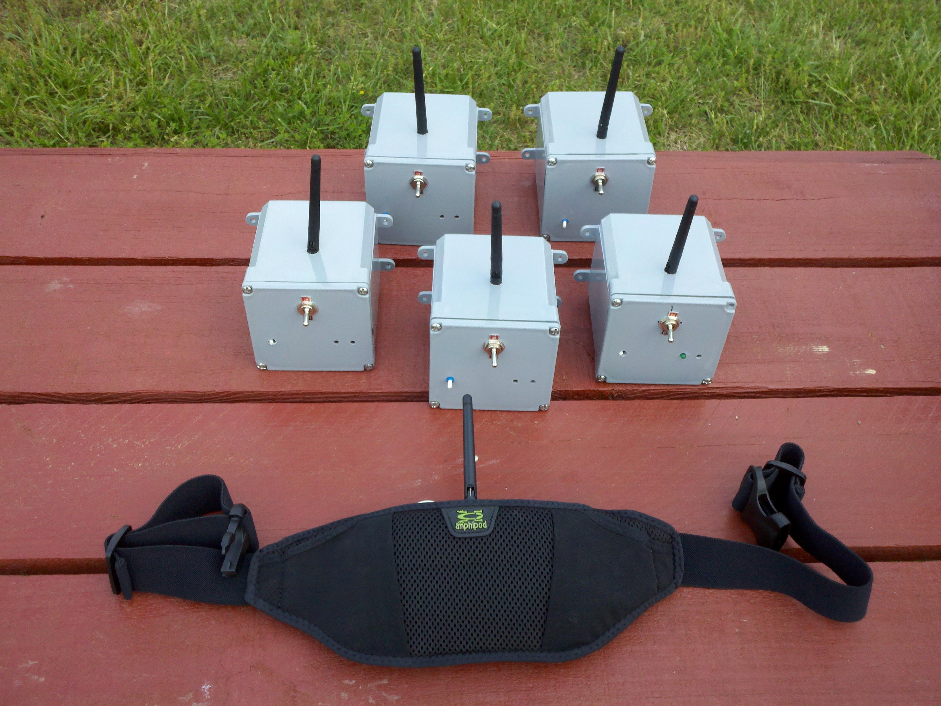
Figure 1: The five radio beacons, with speakers mounted inside, that get mounted on weaving poles, and one radio detector that is worn by the use on a hip belt.
When riding, he follows a course around an arena that is marked by weaving poles. Riders with visual impairments have difficulty knowing when they reach a pole, so volunteers tap the poles to indicate their position using sounds. This task occupies volunteers’ time and prevents them from assisting other riders. I have developed a wireless navigation system (figure 1) that automatically emits audible beeps when the rider approaches a pole. This will enable Jim and riders with visual impairments to navigate their horse independently with minimal input from volunteers.
SUMMARY OF IMPACT
A therapist who works with our client commented that: “The system’s adjustability in terms of range, volume, and tone, as well as its portability, will enable it to be tailored to a wide variety of riders to suit individual needs. Because the device is triggered by the rider, it removes the instructor and volunteers from the loop and allows the rider more independence than would otherwise be possible.” Our client indicated that he finds the system to be helpful in indicating the location of the weaving poles. When using the system, he was able to independently guide the horse along a course.
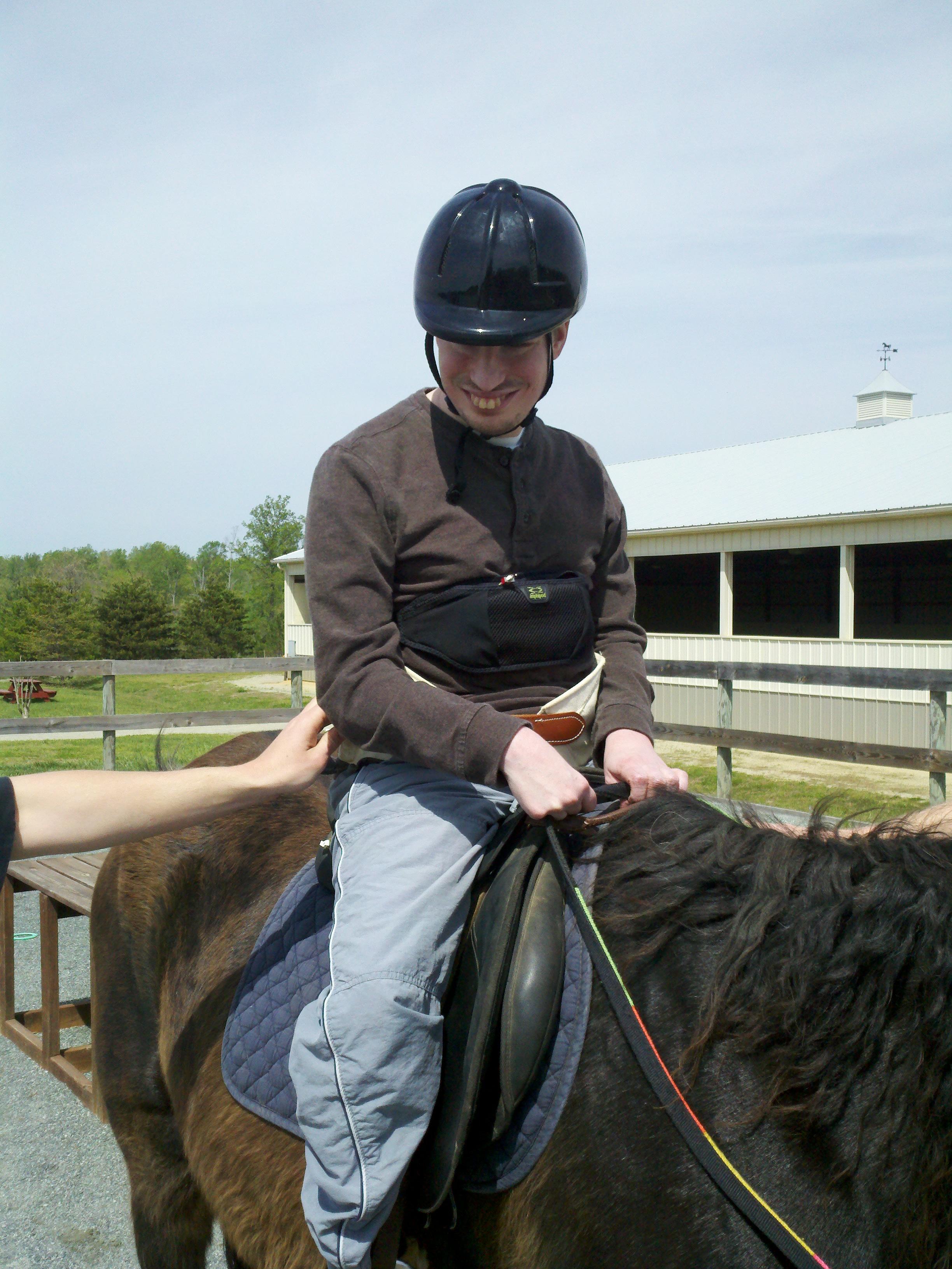
Figure 2: The client wearing the hip belt and preparing to ride in the outdoor arena.
TECHNICAL DESCRIPTION
The system is comprised of two devices: a radio beacon worn by the rider and a set of 5 radio detectors, each mounted to a weaving pole. As the rider approaches a pole, the detector will begin producing a tone so that the rider knows the relative location of the pole. When the rider passes the pole, the detector will silence as it loses radio contact with the beacon. This process repeats as the rider moves around the course.
Every beacon and detector contains a radio transceiver (nRF24L01, Nordic Semiconductor) that operates in the 2.4 GHz range. The beacon transmits a signal five times/second, while the detector’s transceiver constantly listens for the beacon’s signal. The system relies on microcontrollers (PIC 18F2420, Microchip, Inc.) to setup the communication protocol process the data exchanged between the radio transceivers. Communication between the transceivers and microcontrollers uses SPI, a serial protocol for exchanging data. A computer program was written in the C programming language to implement the SPI protocol on the microcontroller and perform the signal strength measurements. A custom circuit board was designed and fabricated for both the beacon and detector.
A. The Beacon
The beacon is worn around rider’s torso and its electronics are contained inside an “amphipod belt”. The beacon’s circuitry is encased in an acrylic housing and is principally comprised of the radio transmitter, antenna, and the microcontroller. Other circuitry includes a voltage regulator to protect the circuit and LEDs to indicate the beacon’s transmission power level.
The beacon’s microcontroller configures the radio transceiver to act as a transmitter. The microcontroller controls all aspects of the transmission, including the transmitter’s power level, the data sequence to transmit, and the number of transmissions per second. The transmitter’s signal strength can also be adjusted by the user; this feature allows the range of the system to be optimized for particular activity.
B. The Detector
The detector includes the same electronic components as the beacon, but the microcontroller is running a different program and the circuitry also includes a speaker to generate audible tones. The detector’s components are mounted inside a marine grade 4x4x4” plastic electrical box which is attached to a weaving pole using bungie cords.
The detector’s microcontroller is programmed to continuously search the airwaves for the signal transmitted by the beacon. When the detector finds that the received signal has reached a minimum power level, it will begin counting the number of successful data receptions within a given period of time. This measurement is used to determine the signal’s strength. When the signal strength is reaches a critical level the detector will begin sounding, guiding the rider towards the pole. Each detector generates a different sound to make the system less confusing to the rider. The distance at which the sounding begins is proportional to the beacon’s transmission power and can be set for distances between 5’ and 25’.
The total cost of this project is $421 for 1 detector and 5 beacons.
University Operator: (919) 962-2211 | © 2024 The University of North Carolina at Chapel Hill |