Designers: Morgan Leeds and Furat Sawafta
Client Coordinator: Barry Wright, Community Workforce Solutions
[youtube]http://www.youtube.com/watch?v=EQ-rBYtswko[/youtube]
INTRODUCTION
Todd and Sarah (pseudonyms) are adult employees who work at Community Workforce Solutions (CWS), a local organization based in Raleigh, NC, that employs people with disabilities. Each of the clients would like to be able to perform their jobs independently and rapidly, as they get paid according to the amount of work that they can complete.
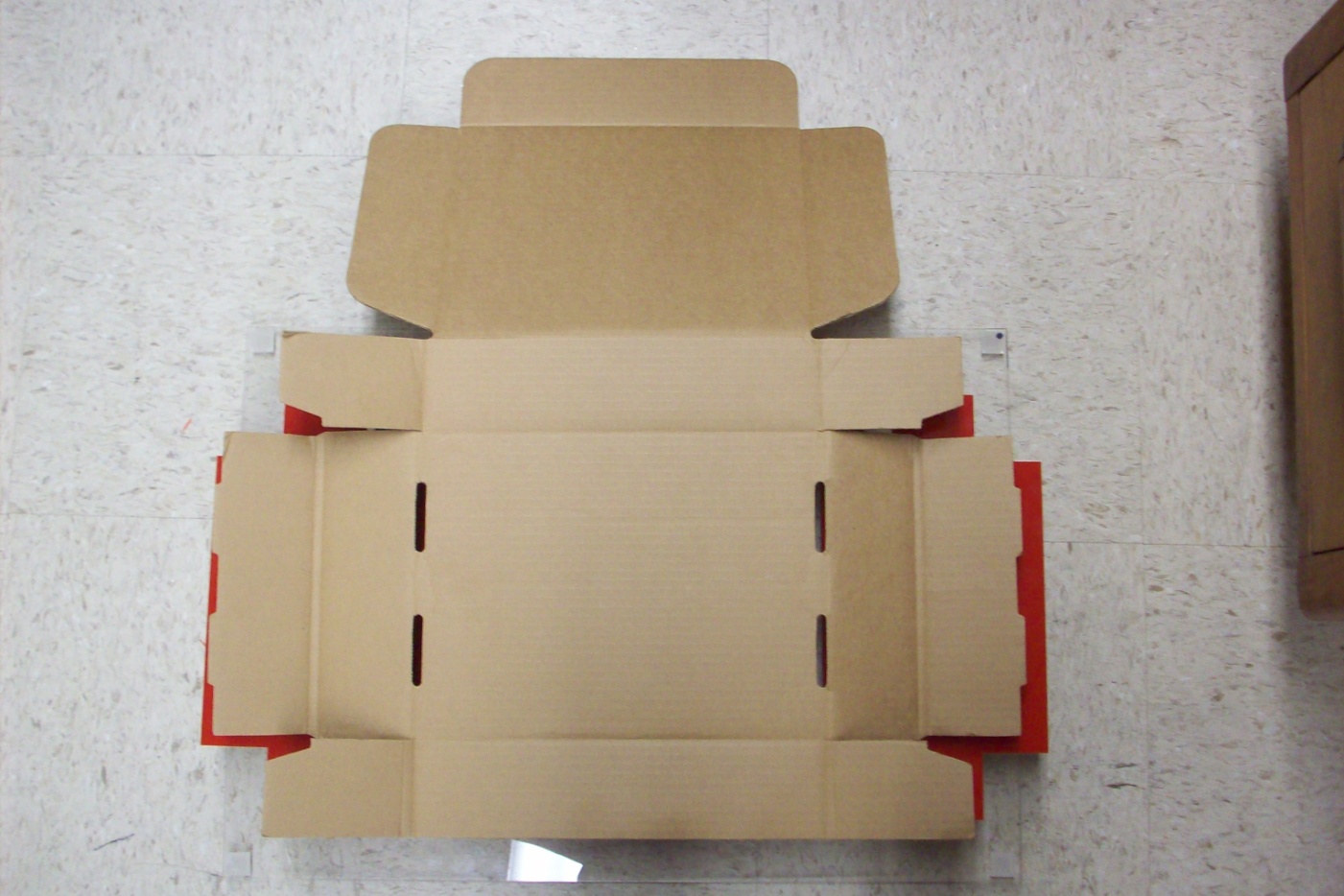
Figure 1a: The flat cardboard box template, which is the starting point for this task
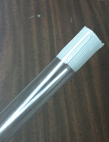
Figure 1b: The plastic channel tube with two pieces of filament tape properly placed over one end
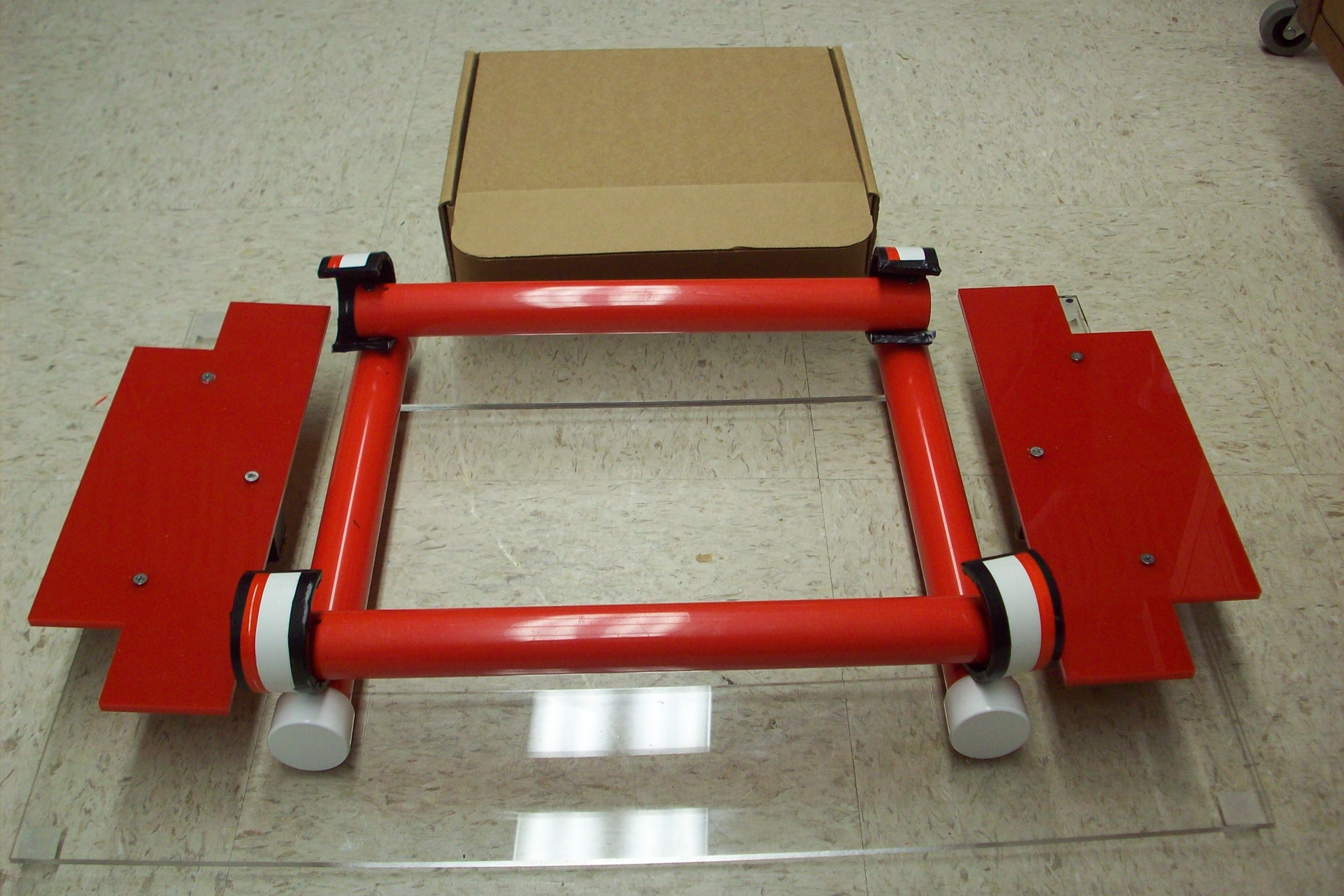
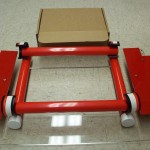
Figure 2: The box folding device, with a folded box in the background
One of Todd’s tasks at CWS is to assemble a cardboard box in an eight-step process from the initial unfolded cardboard template (figure 1a). Because of his cognitive disabilities, he has difficulty with multi-step processes, and needs to be reminded which step comes next. We developed a box folding template that reduces the process to only four steps, making this task much easier for Todd (figure 2).
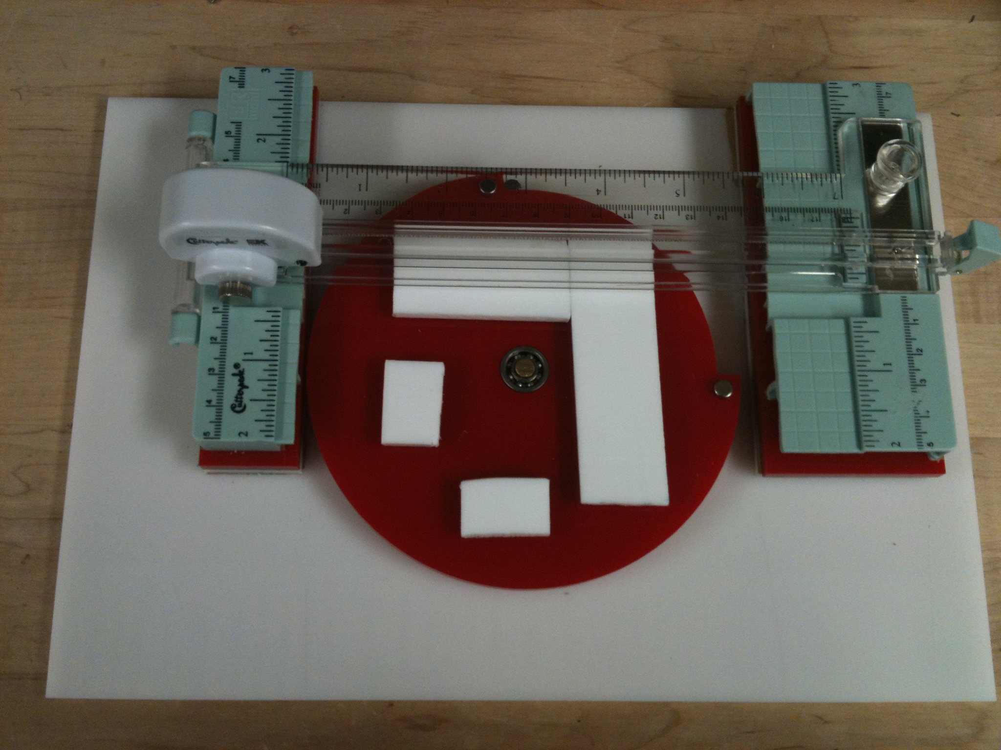
Figure 3: The tuntable cutting device. The tape gets pulled from top to bottom across the two pieces of teflon, and the rotary cutter moves from left to right to cut the tape.
One of Sarah’s tasks is to cut two pieces of reinforced filament tape and place them in a cross pattern over the end of a clear plastic tube (figure 1b). She has limited fine motor control, which results in some shakiness. As a result, she cannot easily grasp and use cutting tools, so it is difficult for her to cut tape, in particular filament tape because it is resistant to cutting. It is also difficult for her to place the tape over the end of the plastic tubes due to her poor motor control. We developed a cutting device that makes it simpler to cut the tape and helps to create the cross pattern (figure 3).
STATEMENT OF IMPACT
Before the completion of our devices, neither Todd nor Sarah could independently complete these tasks. With the Box-Folding Assistant and Turntable Cutting Device, they can complete their tasks and do so in a timely manner that will allow them to make more money per hour. Barry Wilson, production manager of CWS, stated: “I think this will really help Sarah and Todd. They want to do anything they possibly can do; a lot of times they have to have an assistant person helping them out, telling them what to do. These devices are going to help them learn to do it by themselves, which give them more and more confidence.” Todd exclaimed, “I like it, I’m the man!” after several successful rounds of folding boxes. With regards to the turntable cutter, Sarah explained “it is much easier than using scissors.”
TECHNICAL DESCRIPTION
A. Box folding assistant
The box folding assistant consists of four connected pieces of 1.3″ PVC piping that form a square inset. An unfolded box is placed above the inset, and the user then presses the center down through the PVC supports. The curvature of the PVC pipe assists in creasing the box template as this motion is completed. Four shorter sections of pipe at the four corners of the device encourage the short side flaps to fold upward first, facilitating the rest of the box folding task. This forms the basic shape of the box, all in one step.
To help with the placement of the box template over the folding assistant, three acrylic pieces that mimic the shape of the box template are placed around the folding assistance component. This helps instruct the user where to place the box before beginning the folding process. The acrylic pieces stand at a height of two inches, offset from the side of the box folder by 1.5” inches on either lateral side. The shape and bright color of these pieces both draw the user’s attention and allow user to quickly recognize how to align the box during device use.
The final component aids the user to crease the unfolded template. A flat acrylic piece in the shape of a cross with a handle for easy use is provided, as seen in Figure 2b. This component aids in creating the creases along several flaps. In particular, the 0.177” thickness of the acrylic corresponds to the width of the double-crease of the side flaps. This allows the user to fold the flap over the acrylic to easily form the double-crease, which had been the most difficult part of creasing the box for our clients.
B. Turntable Cutting Device
The turntable cutting device consists of a turntable, a handle, and a shuttle with a rotary cutting blade. To operate this device, the user pulls one piece of tape across the Teflon pieces on the turntable, and then runs the shuttle along the track across the tape, as with a paper cutter. The user then rotates the turntable 90˚ to repeat the process for a second piece of tape. The tape can then be removed from the turntable, already in the necessary cross pattern and ready to be placed on the end of the tube.
The handle of the device has been created from a commercially available paper trimmer (Cutterpede Mini Paper Trimmer). This paper trimmer uses a rotary blade attached to a rounded shuttle which runs along a track. The track runs the length of the handle (~8in), and the handle of the shuttle must be depressed in order for the blade to extend. This provides a safety guard for the essential blade of the device. We separated the base of this commercial product into three segments: two end pieces, which we kept in our design, and the middle, which we discarded. Both ends of the device were mounted on rectangular acrylic pieces to bring the handle to the level of the turntable face.
The spinning turntable for this device is created from three circular pieces: the base, a spacer, and the turntable face. The acrylic base provides a level area upon which all components of the device are mounted. The uppermost acrylic piece has four Teflon pieces, attached 1” from the center. This forms two orthogonal sets of surfaces over which the tape is cut, allowing the tape to be precut in the cross pattern necessary for this task. To enable rotation of the turntable, we placed a rod through the center of each of the circular components. One ball bearing is inserted into the center of the rotating face. In addition, a stopping mechanism limits the rotation of the turntable to 90 degrees, and magnets help to hold the turntable at the two endpoints of rotation.
By client request, a second face plate was created. At CWS, employees often share jobs, and in this case, one employee would cut the tape to be placed on the channel tube, while the second would place the tape. To accommodate this arrangement, the second face plate was designed to allow repetitive cutting of single 3” pieces of tape. Two parallel pieces of Teflon are attached to the face 3” apart, allowing the user to rapidly produce single pieces of tape. This plate replaces the rotating turntable face and is immobilized as it locks over the stopping mechanism.
The total cost of both devices was $200.
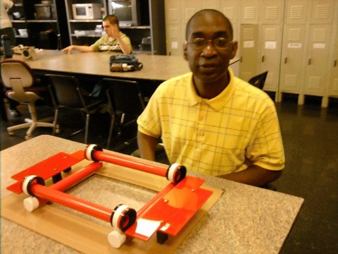
Figure 4a: client using the box folding device
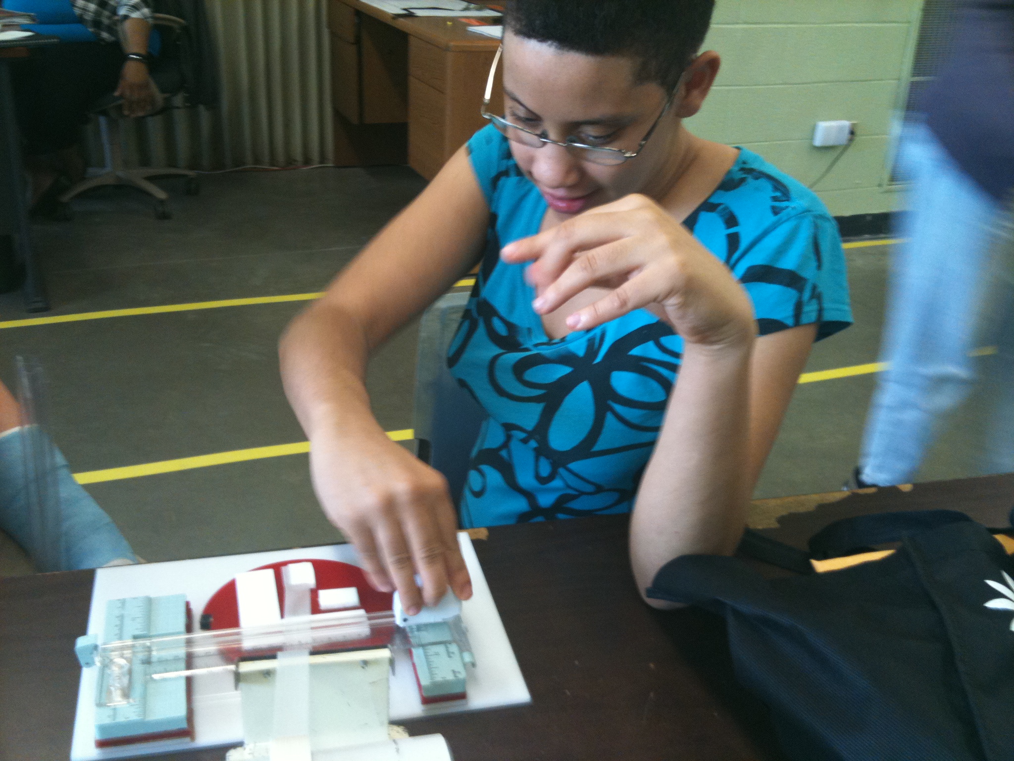
Figure 4b: client using the turntable tape cutting device
University Operator: (919) 962-2211 | © 2024 The University of North Carolina at Chapel Hill |