
Designers: Jacob McPherson and Jeffrey Whittaker
Client Coordinator: Luanne Holland, Speech and Language Pathologist, Durham Public Schools.
INTRODUCTION
Students with severe cognitive and motor impairments are unable to easily interact with their environment. Their motor impairments limit their ability to navigate through the classroom to obtain books and toys, while their cognitive disorders limit their ability to choose between items. Not only does this affect their independence, but it also places a burden on the teachers, who must spend time determining which toy or activity that the student would like to have. The goal of this project was to develop a device that a child could use to select one of four different toys while remaining seated or standing in the same position. The device should also provide audio and visual feedback.
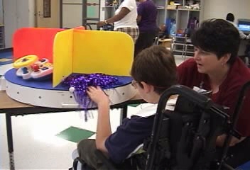
Figure 1. Client using the Lazy Susan.
To address these needs, we developed an electronically actuated Lazy Susan (Figure 1) for elementary school students with severe and profound disabilities. The Lazy Susan presents the child with a single toy. A partition blocks the view of other toys on the device, so that the user is not distracted. When the student presses a button, the device starts to rotate, and it stops when the next toy is presented to the user.
SUMMARY OF IMPACT
According to Luanne Holland, Speech and Language Pathologist, the device succeeded in increasing the student’s independence by giving them direct access to the items they desired and by decreasing the amount of teacher intervention necessary. It eliminated the need to navigate the classroom to obtain an object, and prevented confusion in choosing from among a group of items.
TECHNICAL DESCRIPTION
The Lazy Susan consists of a 36” diameter top disc, a similar shaped base, and a thin sheet that is wrapped around the perimeter. All items are made of Plexiglas. A DC motor, located inside the device, rotates the top disc. The disc rests on a bed of 10 casters that allow for smooth rotation while holding up the weight of the disc and toys (see figure 2). The teacher can connect up to three external, commercial switches to the device via standard audio jacks. When one of these switches is pressed, the device turns on the motor, initiates the first audio feedback message, “GO,” and turns on the LEDs that are around the perimeter of the device. The device will continue to rotate, with the LEDs on, until the next toy is positioned in front of the user.
The partitions on the top of the device allow the Lazy Susan to be sectioned into halves or quadrants, and the device will automatically sense which mode it is in and rotate either ½ turn or ¼ turn accordingly. There is a tab on the bottom of each partition; the device detects when the tab passes in front of a photointerrupter, and stops the motor accordingly. Then, it plays the final audio feedback message, “STOP”, and it turns off the LEDs. The device then resets itself, and is ready for the next trigger.
All circuitry is housed within the device itself, and the microprocessor, speaker, other ICs and the PCB are all contained within an internal project box (see figure 2). User controls for power, volume, and LED on/off are contained in an external box, accessible to teachers but not to students.
The device is battery powered and therefore does not need to be tethered to a wall, thus increasing its mobility. The low profile of the Lazy Susan allows it to be placed on the floor or on a table, depending on the child’s needs, while the bottom of the device is covered with non-slip neoprene to prevent unwarranted movement. The neon colors of the partitions help to retain the interest of the children.
The cost of the project is approximately $370.
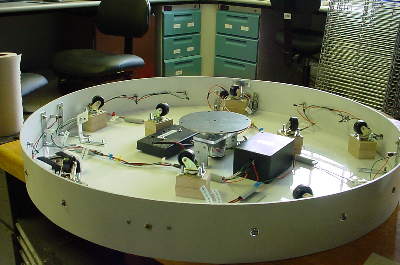
Figure 2. Lazy Susan with the top disc removed. The DC motor is in the center, along with the electronic circuitry box. There are 10 casters distributed around the device to hold the weight of the top disc. LEDs are along the perimeter.
University Operator: (919) 962-2211 | © 2024 The University of North Carolina at Chapel Hill |